
Failure Analysis and Life Assessment
RMS provides comprehensive failure analysis, root cause determination and remaining life assessment for critical components and materials. Our multidisciplinary approach combines advanced testing, metallurgical expertise and engineering evaluation to deliver actionable solutions.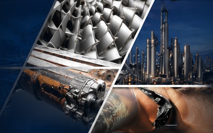
TYPICAL COMPONENTS WE INVESTIGATE
- Pressure vessels & piping components
- Heat exchangers & boilers
- Rotating equipment (turbines, compressors, pumps)
- Storage tanks & structural members
- Weldments & fabricated parts
- Fasteners, bolts & critical hardware
- Castings, forgings & rolled products
- Coatings, linings & claddings
- Concrete & refractory materials
- Polymers & composites
We examine components from a wide range of industries including oil & gas, petrochemical, power generation, aerospace, transportation, mining and manufacturing.


OUR FAILURE ANAYLYSIS APPROACH
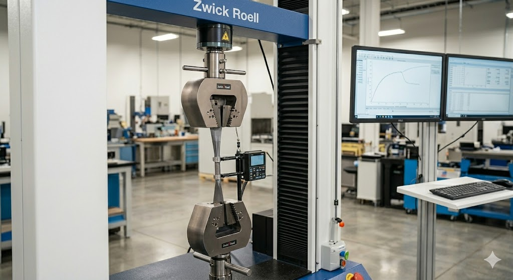
Tensile
- Immediate documentation and evidence preservation
- Review of operational history, inspection records, and technical standards
- Identification of critical variables and risk factors
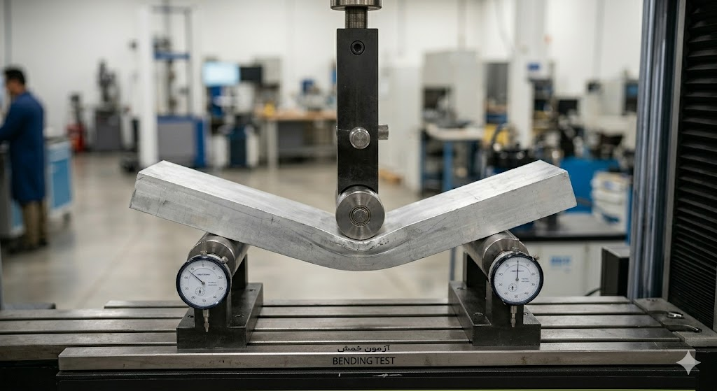
Bending
- Immediate documentation and evidence preservation
- Review of operational history, inspection records, and technical standards
- Identification of critical variables and risk factors
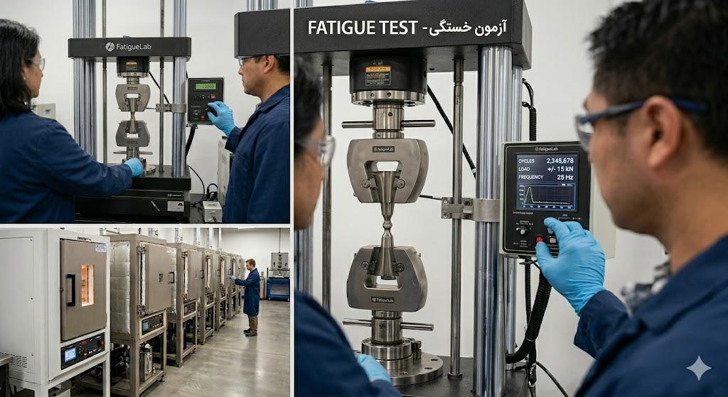
Fatigue
- Immediate documentation and evidence preservation
- Review of operational history, inspection records, and technical standards
- Identification of critical variables and risk factors
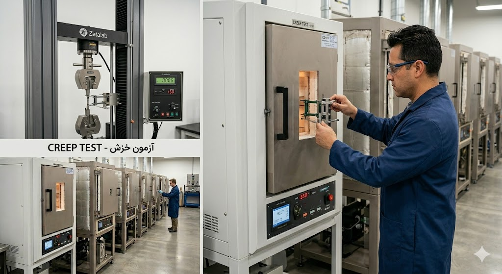
Creep
- Immediate documentation and evidence preservation
- Review of operational history, inspection records, and technical standards
- Identification of critical variables and risk factors
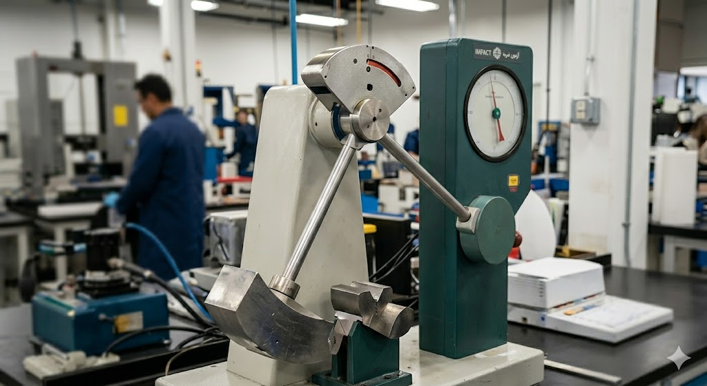
Impact Test
- Immediate documentation and evidence preservation
- Review of operational history, inspection records, and technical standards
- Identification of critical variables and risk factors
ENGINEERING CASE STUDIES
Detailed technical investigations and failure root cause analysis performed by RMS Lab Group across critical industrial sectors.
Case Study 1 : Investigation of the Causes of Failure of the BAC Compressor Impeller in the Air Separation Unit
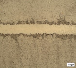
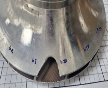
The failure surface of the impeller sample was studied in terms of failure symptoms, manner and rate of progression. The results of the studies showed that the failure first started at the braze connection of the blade to the shroud due to hydrogen embrittlement and as a result of the low-cycle fatigue mechanism, causing the blades to separate from the impeller plate. Then, the failure continued with the propagation of cracks in the radial direction and the thickness of the shroud, leading to the separation of a piece of the shroud. The low-cycle fatigue failure mechanism was associated with the number of on-off cycles or abnormal working conditions
Causes of failure: The inadequate quality and insufficient thickness of the braze layer, as well as abnormal operating conditions, were determined to be the two primary causes of the failure observed in the impeller blades.
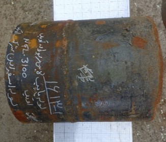
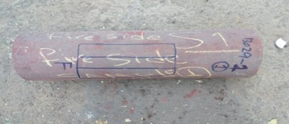
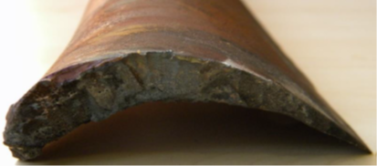
Case Study 2 : Investigation of the causes of the destruction of the 16” Esfarayen NGL-3100 pipeline
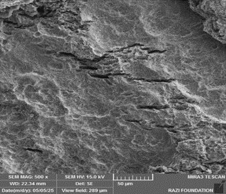
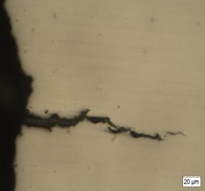
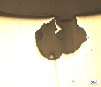
The results of hardness and micro-hardness measurements indicate a high hardness in the crack initiation zone, making the steel susceptible to cracking due to the SSC (Sulfide Stress Cracking) mechanism.
The fracture morphology results indicate the occurrence of quasi-cleavage failure and the development of numerous microcracks in the circumferential direction and in the thickness direction, resulting in the occurrence of the Sulfide stress corrosion cracking (SSCC) mechanism.
The main cause of failure: the non-uniformity of the microstructure and hardness in the pipe at the crack location.
This non-uniformity, resulting from the increased residual stress area during welding, has caused the initiation and growth of an SSC crack from the area of a potential defect on the inner surface of the pipe.
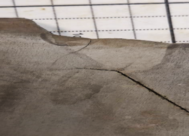
Case Study 3 : The failure analysis of heat exchanger tube
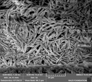
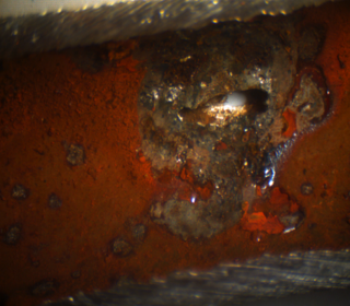
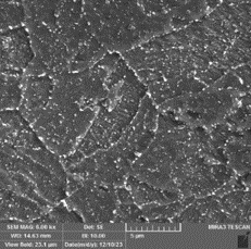
Cauliflower-like sediments were observed inside the holes. Also, in some places, residual effects of rod-shaped bacterial colonies were seen. On the surface around the initial deep hole, numerous shallow and fine pits were observed. EDS results from sediments in the destruction area showed that the presence of high sulfur, iron, and oxygen indicated the formation of oxide (Fe3O4 and Fe2O3) and sulfide (FeS) compounds, as well as high iron oxide in the sediments around the destruction area, and the morphology of the sediments indicated corrosion by sulfate-reducing bacteria (SRB) and even iron-oxidizing bacteria (IOB).
Results: Based on studies conducted, Microbial corrosion (MIC) along with Pitting corrosion, caused by the presence of chlorine, are identified as the two main causes of pipe destruction.
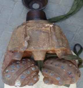
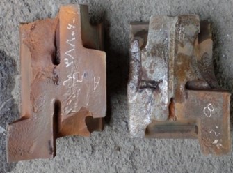
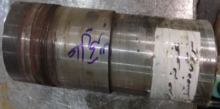
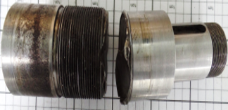
Case Study 4 : Failure Investigation of Tri-Cone Drill Bit 24” KHD425GC'
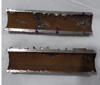
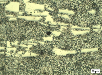
Correlation between fractography results and microstructural and hardness studies indicates that the initial crack propagation occurred in the weld zone exhibiting relatively high hardness.
Macroscopic and microscopic observations, including the presence of an additional weld pass (TIG dressing) and altered weld geometry, suggest elevated residual stress levels in the weld cap region due to welding. Based on the failure analysis, considering three main factors: environment (hydrogen ingress during welding and/or drilling environment containing H₂S), susceptible steel, and sufficient stress level for failure, all three conditions necessary for crack initiation and propagation under hydrogen embrittlement (HE) mechanism were met.
Results: The weld geometry and the presence of an additional pass increased the level of residual stresses, thereby accelerating crack initiation under the hydrogen embrittlement mechanism at the weld surface, specifically at the interface between two passes.
Cracks propagated inside the weld through the mechanical fatigue mechanism, facilitating crack growth and final failure.
Case Study 5 : Investigation of the causes of flange retaining bolt failure
In structural studies, the distribution of chromium carbide particles at the grain boundaries was observed. Also, numerous lap defects were observed at the thread tip and thread wall of intact and broken screws.
The presence of grain boundary carbide particles can be related to the penetration of carbon into the structure or the lack of carbide solution heat treatment. According to the penetration calculations, the presence of chromium carbide particles is related to the high carbon element in the steel and the lack of solution heat treatment in the manufacturing process.
The cause of the failure: The presence of sulfur, wet H2S, and H2 in the fluid has led to hydrogen charging in the steel and, as a result, hydrogen embrittlement of the steel.
The presence of a leak in the system and the contact of the corrosive fluid with bolts of poor quality in terms of microscopic structure (the sensitivity of the steel due to the presence of grain boundary carbides), which leads to hydrogen penetration and the occurrence of hydrogen embrittlement.
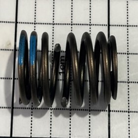
Case Study 1 : The failure analysis of an automotive valve spring
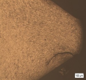
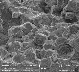
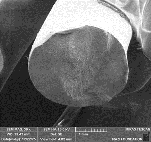
Structural studies indicate the presence of surface defects and microcracks in the spring and primary wire samples. Although the surface defects in the primary wire were shallow, the surface defects and microcracks progressed during the coiling process and reached a maximum depth of 37 µm in some areas. These microcracks lead to a reduction in the fatigue life of the spring.
The main cause of the failure: surface defects and improper heat treatment of the primary wire, which, under cyclic loading, has caused an increase in stress concentration and the formation of fatigue cracks.
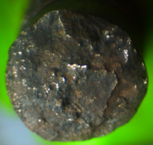
Case Study 2 : Failure Analysis of a Tie Rod of an Automobile Steering System
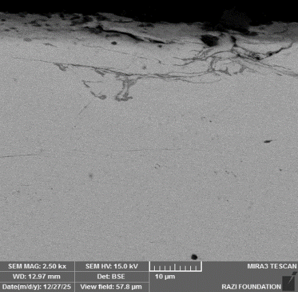
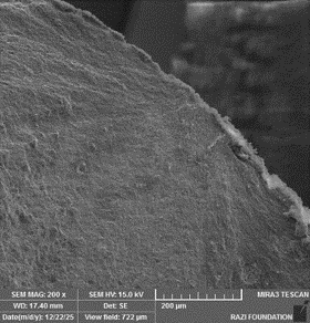
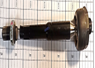
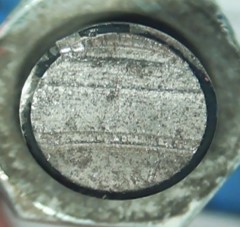
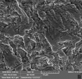
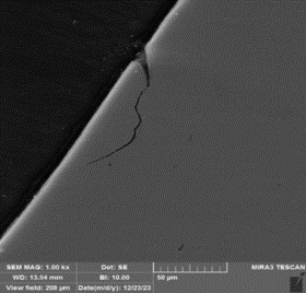
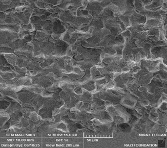
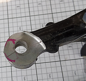
The loss of tensile strength of both failed and intact tie rod samples is related to improper heat treatment of samples during the manufacturing process. Furthermore, the visual inspection showed that the failure occurred at the first and second thread without any trace of bending in the thread part.
The fracture initiation zones indicates the absence of torsional stresses due to improper assembly of the sample. Microscopic studies indicate the presence of laps defects in the loaded flank threaded part of the tie rod with sizes close to and exceeding the standard limits.
The cause of the failure: The presence of peripheral cracks on the edge of the fracture surface is caused by the presence of laps defects on the thread flank.
the small defects produced in the thread roots led to high stress concentrations that favored crack initiation and due to the loading of cyclical stresses and the low strength of steel, they have grown inward under the fatigue mechanism and finally led to fracture.
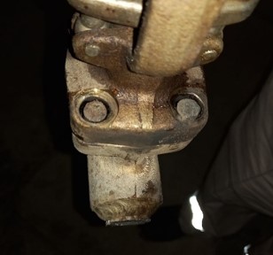
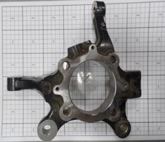
Case Study 3 : Analysis of the Causes of Ball Joint Failure
Microstructural studies revealed that the areas around the defect were decarburized to a depth of about 100 to 150 microns. The formation of a decarburized layer in the defect area indicates that the defect was present as a free surface at high temperature (during forging or austenitizing). The reason for the defect is considered to be related to the forging process, given the high number of defective parts and the uniformity of the defect location, as well as the absence of impurities in the samples examined. The formation of this defect can be due to the forging temperature, the rate of plastic deformation, and the quality of the mold used.
The results of the studies indicate: the observed cracks were the product of thermal stresses and phase transformation stresses induced during the quenching process, which are directly related to the component’s heat treatment conditions.
Undesirable heat treatment conditions, such as an excessively high austenitizing temperature and an overly rapid cooling rate, led to the formation of radial cracks in the component’s stress concentration areas.
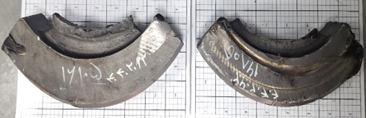
Investigation of the Causes of Counterweight Failure in the EMD645 Locomotive Engine Crankshaft
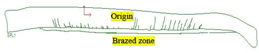
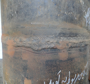
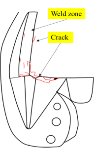
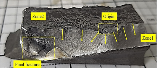
The weld structure at the fracture site consists of a ferrite matrix with grain boundary pearlite and a distribution of cementite particles. In the fracture initiation area, at the root of the weld, some amounts of acicular ferrite were also observed. The results of the fracture imaging studies showed that the fracture surface consists of two separate parts, Zone 1 is a steep and flat fracture and Zone 3 is an uneven fracture and is perpendicular to the counterweight seating location (Zone 2). The fracture first occurred at the steep and flat fracture surface (Zone 1), from the prominent area (Origin) observed at the weld root, in the contact area of the counterweight seating on the pin, as a result of the low-cycle fatigue mechanism at a stress level equal to or higher than the yield strength of the steel and progressed in the circumferential direction of the weld line, with multiple nucleation from the weld root, and then in the transverse direction, by traveling the thickness of the weld, leading to the final fracture of the part
The cause of the failure: Excessive root penetration (identified as a welding defect in the weld root area) and the large contact gap between the counterweight and the pin.
The incorrect weld root geometry, by creating a notch effect, and the excessive distance between the root faces of the welds on either side of the counterweight, resulted in the multiple nucleation of fatigue cracks under the cyclic stresses applied to the joint area.
Materials selection process is characterization and optimization of engineering material properties.
In this process the proper material is selected according to defined criteria of working conditions and desired physical and mechanical properties, and then by optimizing production parameters, it is tried to obtain the most suitable properties with respect to performance, sensitivity as well as economic and the other features of sample.
Achieving this knowledge requires fully exploration of issue by means of mechanical and metallurgical approach on which high level of experience and recognition of the case study is most essential.
Materials characterization and selection department offers research services in the form of following patterns:
-Providing technical identity document for industrial components and engineering materials in the form of reverse engineering projects.
-Consultation in selection of materials and introduction of engineering materials in order to achieve particular purpose of clients.
-Undertaking projects for specifying the manufacturing method and heat treatment cycle.
-Performing projects on selection of materials in order to substitution of the most suitable material for components and equipment with respect to working condition, desirable metallurgical properties, and limitation to procurement of the material.
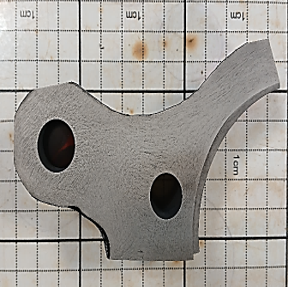
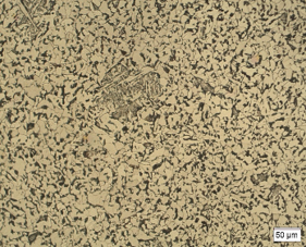
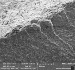
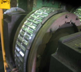
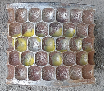
Case Study 1 : Investigation of the Failure Causes of Segments, Related to the Briquetting Process
The surface hardening and matrix hardness of segments were insufficient to withstand the stresses applied to the mold due to improper heat treatment. Consequently, they underwent plastic deformation under operation due to wear and impact.
Therefore, improper heat treatment is the primary cause of failure for segments. It should be noted that continuous primary carbides reaching the surface reduce fatigue strength; thus, a uniform distribution of discrete primary carbides in all regions, especially on the mold surfaces, is necessary.
Metallurgical evaluation of two origin and manufactured shafts and investigation of the causes of failure of the domestically manufactured feed pump shaft
Based on the performed tests, the properties of none of the examined shafts comply with the standard. The high strength and hardness of both shafts indicate a tempering temperature lower than that recommended by the standard. This temperature is estimated to be around 540-600℃ for the domestically manufactured shaft and around 500-550℃ for the reference shaft. The increase in strength and hardness, along with the decrease in ductility and impact energy, in the reference shaft confirms its lower tempering temperature. Increasing the tempering temperature has resulted in a relative improvement in the ductility and fracture toughness of the domestically manufactured shaft.
Our Integrated Engineering Approach
Since substantial amount of money is invested in both industrial equipment and replacement of components before retirement or failure, it is absolutely vital to prevent possible damage. On the other hand, if the lifetime has not been assessed correctly, it can cause early replacement, and therefore additional costs.
The aim of life assessment is not expanding life span, but maximizing reliable lifetime which can be longer than that for designed one.
- Creep life estimation models
- Metallurgical damage assessment
- Fitness-for-Service (FFS)
- International standards: BS 7910 / API 579
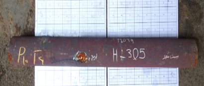
Case Study 1 : Metallurgical evaluation and remaining life estimate for H-305 furnace tube
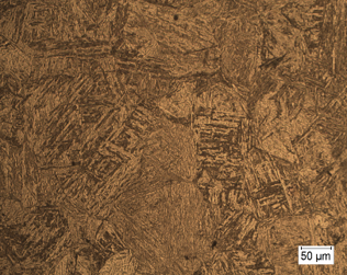
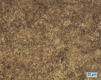
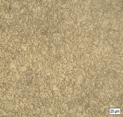
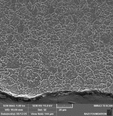
The degradation mechanisms include:
-Spheroidization and growth of carbides,
-Carburization of the internal and external surfaces
-Oxidation and the thickness reduction
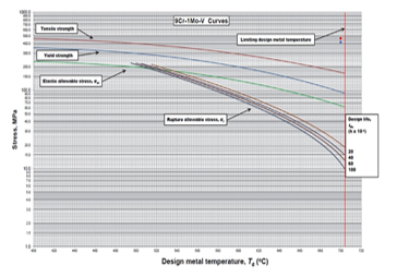
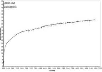
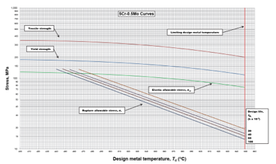
By correlating the hot tensile test results with the Larson-Miller curve for T91 steel and comparing them with the results from the creep rupture test, and assuming a constant operating temperature of approximately 543°C, the continued operation of the submitted tube is feasible.
Based on the Larson-Miller criterion, no significant drop in the tube’s service life has occurred, and an extension of its service life is possible.
Therefore, extending the tube’s service life for a period of 4 years is feasible, assuming a constant performance trend within the declared operating conditions, and assuming similar conditions for corrosion, oxidation, and sulfidation, which would result in a thickness reduction of 1.25 mm during this period.
Case Study 2 : Evaluation of the remaining life of the 3.5-inch P5 tube related to the H-702 furnace
The following issues are considered in estimating the remaining life based on the microscopic structure:
A- Carbide particle density
B- Carbide particle growth in the ferrite matrix and at grain boundaries
D- Formation of creep cavities
Considering the loss of pipe flexibility and the rate of thickness reduction (no local thickness reduction observed in the pipe), it will be possible to extend the service life of the pipe until the end of a repair and maintenance program (4-year period).
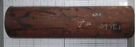
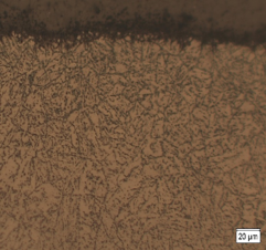
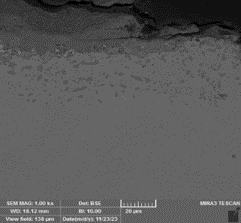
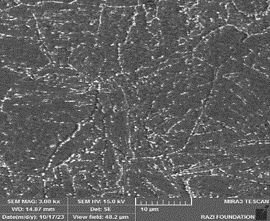
Case Study 3 : Evaluation of the remaining life of the 3.5-inch A106 tube related to the H-702 furnace
The following issues have been addressed in estimating the remaining life based on the microscopic structure:
A- Pearlite spheroidization
B- Particle growth in the ferrite matrix and at grain boundaries
C- Increase in the denuded zone width
D- Formation of creep cavities
Therefore, if operation continues at operating temperature and pressure conditions and considering the same corrosion rate during continued operation (controlling the amount of sulfur in the fluid composition), it is possible to extend the life of the pipe up to a period of four years.
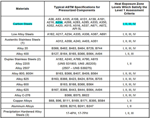
Case study 1– API 579-1-FFS , part 11(Level 1 Assessment) : Feasibility study of continued operation of 6-inch WPB elbow exposed to fire related to Isomax unit equipment
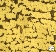
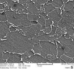
Based on visual inspection and studies conducted, deposits with predominantly black and dark orange colors were observed on the external surface of the elbow sample.
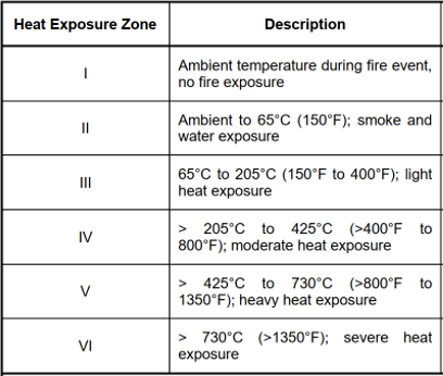
According to Table 11.8, API Standard 579-1 (2021), the formation of this type of deposit usually occurs in the temperature range of 540°C-870°C.
In Level 1 Assessment, Microstructure degradation effects were observed on the external surface of the elbow, but it was not accompanied by mechanical degradation.
Accordingly, it is possible to return the part to service conditions. However, considering the reduction in thickness of the elbow during 30 years of operation and the calculated corrosion rate, it is recommended that the remaining life estimation steps be carried out taking into account the design calculations.
Case study 2– API 579- FFS Assessment
Identification of damage mechanism and remaining life assessment for the tubes of Furnace H-107
Calculations for the minimum required wall thickness based on API 579-Part 5 and API 530 standards were performed.
Considering the Corrosion Allowance δCA and the corrosion rate, the minimum required thickness for the tube was calculated to be 1.52 mm.
If the operation continues under the same temperature and pressure conditions and assuming a similar corrosion rate (with no change in H₂S concentration and fluid composition), the service life of the tube can be extended for an additional four-year period.
Service life | 10 years |
Nominal Diameter | 5” SCH 80 |
Material | ASTM A 106 Grade B |
Fluid | Natural gas (Methane, CO2, H2S, N, H2O) |
Corrosion Allowance | 3 mm |
Design Temperature | 360 °C |
Design Pressure | 8.19 MPa |
Case study 3– API 579- FFS Assessment
Metallurgical investigation and estimation of remaining life of P9 Radiant tube
According to the observation of sulfidation traces on the internal surface, based on the Couper-Gorman diagram, at a working temperature of 480 °C (896F), depending on the change in the H2S content from 0.03-0.05 mol%, the steel corrosion rate is about 45-55 mils per year (equivalent to 1.14-1.4 mm per year).
In the calculations to estimate the life, due to the lack of access to the initial thickness of the pipe and taking into account the thickness of the oxide layer on both the internal and external surfaces, as well as the thickness of the sulfidation layer, the Hoop stress for the pipe was calculated:
By extending the service life of the pipe for 12 years and assuming a constant operating trend within the declared conditions and assuming similar corrosion, oxidation, and sulfidation conditions, resulting in a total thickness reduction of 0.8 mm during this period, the Hoop and Von Misses stress levels are calculated to be 15.10 MPa and 13.08 MPa, respectively, which is much lower than the stress required for rupture.

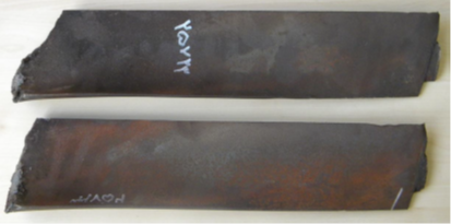
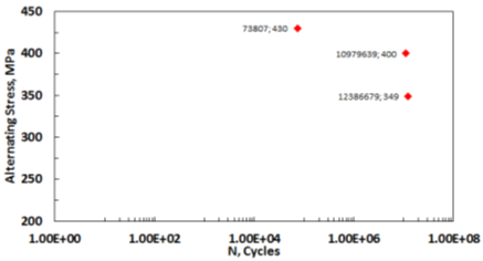
Case study 4– BS 7910-FFS Assessment Estimation of the remaining life of the fifth row blades of the low pressure unit of the steam turbine
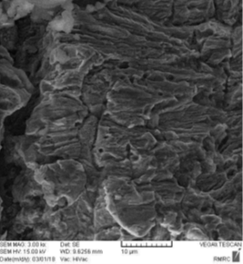
This type of failure can be categorized into 5 steps:
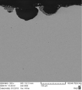
Step 1- Corrosion pit nucleation
Step 2- Pit growth
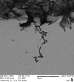
Step 3- Fatigue crack nucleation from pits
Step 4- Small fatigue crack growth
Step 5- Large fatigue crack growth
Step 6- Final failure
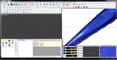
Calculations of life estimation based on fatigue crack growth:
If the crack length of the blade growth threshold is assumed to be 2052 mm, then cracks of 202 mm in length are in the growth stage.
Thus, the number of cycles required for the growth of these cracks was calculated based on the BS 7910 (2013) A1 (2015) standard. Here, it was assumed that a crack with dimensions a=0.25 mm and 2c=0.35 mm grows until failure.
According to this standard, the crack growth rate is defined using the Paris equation.
In this equation, da/dN, the crack growth rate, ΔK, the stress intensity and the constants m and A were defined using the references as 2.95×10⁻⁹ and 2.4, respectively
According to the results obtained from the tests, the remaining life of the fifth row blades of the steam turbine was estimated based on the corrosion-fatigue mechanism, taking into account the thickness reduction.
Using the results obtained from the calculations based on the BS 7910 standard, the linear fracture mechanics method and the accumulation of fatigue defects, the remaining life of the mentioned blades has ended and their continued service will be accompanied by a lot of risk.
In other words, due to the metallurgical conditions and fatigue properties of the blades, it is not possible to reuse them.
Case study 5-Simulation Using Abaqus
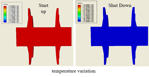
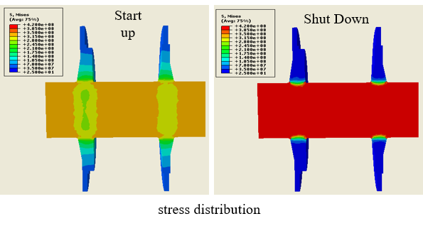
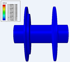
Case study 5-Simulation Using Abaqus
The results of temperature variation and stress distribution for both start-up and shut-down conditions of steam turbine rotor.
In this study, a Coupled Temperature–Displacement (Transient) analysis procedure was employed to achieve the objective of the simulation.
The initial temperature of the entire component was assumed to be 25 °C.
The simulation was performed in two analysis steps:
Start-up phase: The temperature was increased from 25 °C to 400 °C over a period of 4 hours.
Shut-down phase: The process was modeled in reverse, with the temperature decreasing from 400 °C back to 25 °C over the same duration.
Remaining life assessment of equipment and parts which are constantly degrading in working condition as well as determining technically proper condition and ensuring safety of staff are all the matters with crucial importance in various industries.
Fitness for service (FFS) is the effective method for optimizing the conservation and implementing the required measures in order to improve long-term economic performance of industrial equipment such as pressure vessels, tubes and storage tanks.
-Corrosion assessment
-Nondestructive tests
-Finite element analysis for assessment of component
-Consultancy service with precautionary approach in order to prevent failure